STIFFNESS MATRIX METHOD
LEVEL: Undergraduate (B. Tech )
In this method you have two major stages
- Generation of stiffness matrix
- Use of stiffness matrix to solve structural analysis problems
The stiffness matrix can be generated using either direct method OR transformation method
Transformation method
The transformation method has the following steps
- Generation of member stiffness matrix [Km
- Generation of transformation matrix [C]
- Obtaining system stiffness matrix using [CT][Km][C]
EXAMPLE: Truss Analysis using Stiffness matrix method
Step2: Write member stiffness matrix.
For truss each member has 1x 1 stiffness matrix [AE/L ]
Step3: Write transformation matrix.
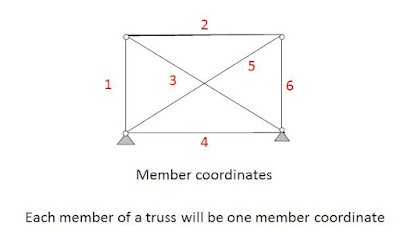
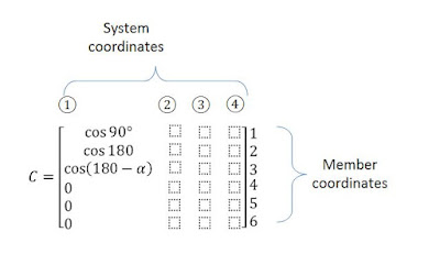
So, the size of transformation matrix will be (no. of members x no. of DoF). For determining the elements of each column of C matrix, give unit displacement along SYSTEM coordinates and find displacements along member coordinates (Axial extensions)
It can be observed that when unit displacement is given as shown above, the members 1,2,3 gets deformed. So, non-zero values will be there ONLY in rows 1,2,3 of Column 1. These non-zero values will be equal to cosθ , where θ is the anti-clock wise angle made by the rotating member from the positive x-axis direction. (see left portion of the figure below)
For member1, the value of θ is +90͒, for member2, the value of θ is 180͒, for member3, the value of θ is 180͒-θ. (see figure below)So, the first column of C matrix will be
For the second column of C, the deformed shape will be as shown below
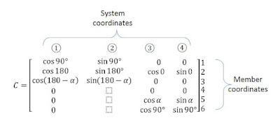
In this case also, the value of θ for various members will remain same, because the unit displacement is occuring at the same joint. But, since the unit displacement is in y-direction, the extension of each member will be sinθ. So, the second column of C matrix will be
For the third column of C, the deformed shape will be as shown below
In this case, the mebers 1,3,4 are not deformed, and so will have zero extensions. FOr mebers 2,5, 6 the angle θ will be 0͒, α, 90͒. Since the unit displacement is horizontal, the extension will be cosθ. Thus the third column of C will be
The deformed shape for the fourth column will be obtained by giving unit displacement along system coordinate 4 and zero displacement alon all other system coordinates
In this case also, the angle θ will remain same as in the previous case (because the unit displacement occurs at the same joint). But, the extension becomes sinθ, because the unit displacement is given in the vertical direction. Thus, the C matrix will be as follows
Final C matrix will be
The system stiffnes matrix will be [K]=[CT][Km][C]


