Showing posts with label UG- Indeterminate Beams. Show all posts

Friday, 7 May 2021

Analysis of continuous beams by force method

 In this post, I explained the analysis of continuous beam. Continuous beams are indeterminate beams, and their analysis (using force method) requires use of deformation conditions (known as compatibility conditions). In the following video the derivation of the Clapeyron's theorem of Three Moments is explained This follows the general procedure of force methods


The application of clapeyron's theorem of three moments is illustrated using two examples in the video below.


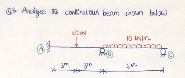
IN the write-up that follows, the analysis of a continuous beam with fixed end supports is discussed. If the end support is a fixed support, it needs to be replaced with a fictitious span of infinite moment of inertia. This procedure is illustrated as follows

 IN the above problem, the support A is fixed. So, that support is replaced with a fictitious span A'A. The fictitious span (A'A) will not have any load, and its span is not needed;although it can be assumed to be of finite value
 In the above figure, the BMD of each span is also shown. Note that, in this procedure, each span is assumed to be simply supported. Since, Clapeyron's Theorem of Three Moments (TTM) is applied for two-spans at a time, we will apply TTM for spans 1 & 2, then for spans 2 & 3.
 Note that M1 is not needed. M2 is equal to fixed end moment at A, MA, and M2 is equal to MB . Now we can apply TTM to span A'A&AB as follows
Then TTM can be applied to next two spans, AB-BC

Solving equations 1&2 simultaneously,
After the support moments are obtained, the vertical reactions can be determined by simple application of equilibrium equations.

BMD of the continuous beam can be drawn by superimposing the simply supported BMDs caused by given loading and the simply supported BMD caused by end moments
The theorem of three moments can also be applied to propped cantilever beams and fixed beams as illsutrated below


Analysis of fixed beams by force method

  Analysis of Fixed beams using Force method

The following video explains the force method for analysis of fixed beams


Further problems of Fixed End Moments: 

          In all problems, the basic principles are as follows
                 1) area of M/EI diagram = 0
                 2) moment of M/EI diagram about any of the support = 0

This is a problem in which the loading consists of a concentrated moment or couple

 Restating the basic principles of analysis of Fixed beams, as below

For applying these basic principles, we need the M/EI diagram of the beam. This can be drawn by considering the Fixed beam as a simply supported beam with given loading and simply supported beam with the load of (redundant) support reactions. Hence, the 1) M/EI diagram for simply supported beam with M0 loading and 2) M/EI diagram with the loading of support moments are drawn as below. Note that the M/EI diagram due to support moments is same in all problems.

 Using the above figures and their geometric properties, the area of the figures is determined and equated to zero as shown below

 Similarly, the moment of the figures is determined and equated to zero as shown below


 Now substitute equation 1 , to eliminate MA, as follows
 By substituting this expression for MB in equation 1, we can determine the expression for MA also. This completes the problem

Determining Fixed End Moments under distributed load

Recall that the Fixed End moments for the following case is given as below


Using the above result, the Fixed End Moments for any case of distributed load can be determined as below. For example, any distributed loading can be considered as a series of differential concentrated loads (shown shaded in the figure below).

The concentrated load corresponding to the shaded portion of distributed load is qxdx (=P). This load is acting at a distance of x (=a) from A and L-x (=b) from B. On substituting these values of P, a and b in the expression above, we get the end moments caused by the differential load. IN the figure below, the support moment at A is evaluated


On integrating the above expression we get the support moment due to the whole distributed load
The following example illustrates the application of the above procedure for fixed beam with UDL. Note that UDL is a distributed load having constant intensity. So, qx=w is a constant with respect to x.

Similarly, MB can be evaluated. It can be concluded that MB=MA for this case of symmetrical loading.

Analysis of propped cantilever beams by force method

 In the video below, I explained the application of force method for analyzing indeterminate beams of type "Propped cantilever beams"


Let us see another example problem, which is slightly more difficult.


This is the example of a non-prismatic propped cantilever. Non-prismatic beam is a beam whose cross-section is not uniform throughout. In the above figure the cross-section has moment of inertia of '2I' in the first 3m and 'I' in the next 2m. Let us say the fixed end is A and the prop is provided at B.

The deflection diagram (or elastic curve) looks as shown below. Note that there is some slope at B, but deflection is zero at B. whereas at A, both deflection and slope are zero. We can conclude that the vertical distance of B (after deformation) will be zero from the tangent at A (tangent at A is horizontal line AB). This is the compatibility condition for this problem.


From Moment area theorem-II we can conclude that the moment of M/EI diagram is zero about B.For drawing the M/EI diagram we have to draw 1) M-diagram or BMD for RB and 2) M-diagram or BMD for given loading, and then add them up. The figure below shows the M-diagram and M/EI diagram due to RB. At the section where cross-section changes suddenly, there will be two values of M/EI diagram, one using 2I in place of I, and another using I in place of I. Note the change in shape of M/EI diagram due to non-prismatic nature of beam


Similarly, the M-diagram (BMD) due to UDL is drawn and when divided with EI it give M/EI diagram. Again, due to the non-prismatic nature, the M/EI diagram has a sharp jump at the place where I is changing.

For determining the moment of the M/EI diagrams due to RB and UDL, we need the knowledge of areas and centroids of the figures as shown below.


Using the above areas and centroids the moment about B of the M/EI areas between A and B can be calculated as shown below


After determining RB, other support reactions VA and MA can be obtained based on vertical equilibrium equation and moment equilibrium equation. By this we should get, VA= 47.89 kN and MA=51.75 kN-m