Design of industrial building consists of the design of the following components.
This post deals with the design of the components starting from
Gable rafter.
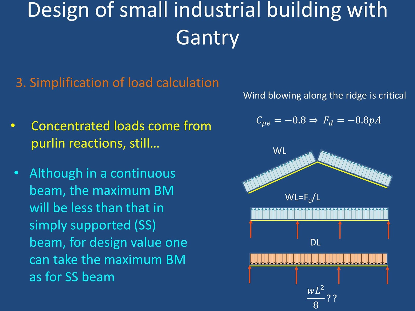
The factors governing the calculation of span length, dead load and wind load are given below
Dead Load : Roof sheeting @0.16 kN/m2, purlins @0.08 kN/m, self wt of gable rafter @ 0.1 kN/m
Live load of 0.5 kN/m2 can be assumed
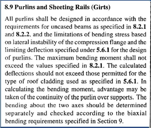
Wind Load: IS 875-PartIII prescribes the value of C
pe as -0.8 as given below
Design moment: As mentioned in the figures above, the design moment can be taken as if gable rafter is simply supported between the columns. This is conservative and simplified approach.
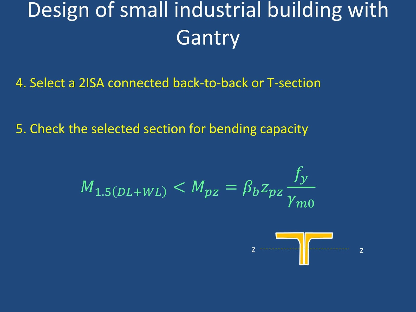
Design moment capacity: Plastic moment capacity of a selected section can be obtained after locating the palstic neutral axis, as below
Design of Side rails/ Wall girts:
Side rails suporting the wall sheeting are designed as laterally supported beams subjected to biaxial bending as prescribe in IS 800: 2007
Design loads are calculated based on the design values shown in the above figure. The external wind pressure coefficient is given below in IS 875-part III
Design moments in both directions can be obtained considering the continuous span to be simply supported between the columns
Design plastic moment capacities in both directions can be obtained directly from plastic section moduli given in IS 800-2007
The interaction formulae given below can be used to check this beam under biaxial bending