Friday 7 May 2021

Analysis of continuous beams by force method

 In this post, I explained the analysis of continuous beam. Continuous beams are indeterminate beams, and their analysis (using force method) requires use of deformation conditions (known as compatibility conditions). In the following video the derivation of the Clapeyron's theorem of Three Moments is explained This follows the general procedure of force methods


The application of clapeyron's theorem of three moments is illustrated using two examples in the video below.


IN the write-up that follows, the analysis of a continuous beam with fixed end supports is discussed. If the end support is a fixed support, it needs to be replaced with a fictitious span of infinite moment of inertia. This procedure is illustrated as follows

 IN the above problem, the support A is fixed. So, that support is replaced with a fictitious span A'A. The fictitious span (A'A) will not have any load, and its span is not needed;although it can be assumed to be of finite value
 In the above figure, the BMD of each span is also shown. Note that, in this procedure, each span is assumed to be simply supported. Since, Clapeyron's Theorem of Three Moments (TTM) is applied for two-spans at a time, we will apply TTM for spans 1 & 2, then for spans 2 & 3.
 Note that M1 is not needed. M2 is equal to fixed end moment at A, MA, and M2 is equal to MB . Now we can apply TTM to span A'A&AB as follows
Then TTM can be applied to next two spans, AB-BC

Solving equations 1&2 simultaneously,
After the support moments are obtained, the vertical reactions can be determined by simple application of equilibrium equations.

BMD of the continuous beam can be drawn by superimposing the simply supported BMDs caused by given loading and the simply supported BMD caused by end moments
The theorem of three moments can also be applied to propped cantilever beams and fixed beams as illsutrated below


Analysis of fixed beams by force method

  Analysis of Fixed beams using Force method

The following video explains the force method for analysis of fixed beams


Further problems of Fixed End Moments: 

          In all problems, the basic principles are as follows
                 1) area of M/EI diagram = 0
                 2) moment of M/EI diagram about any of the support = 0

This is a problem in which the loading consists of a concentrated moment or couple

 Restating the basic principles of analysis of Fixed beams, as below

For applying these basic principles, we need the M/EI diagram of the beam. This can be drawn by considering the Fixed beam as a simply supported beam with given loading and simply supported beam with the load of (redundant) support reactions. Hence, the 1) M/EI diagram for simply supported beam with M0 loading and 2) M/EI diagram with the loading of support moments are drawn as below. Note that the M/EI diagram due to support moments is same in all problems.

 Using the above figures and their geometric properties, the area of the figures is determined and equated to zero as shown below

 Similarly, the moment of the figures is determined and equated to zero as shown below


 Now substitute equation 1 , to eliminate MA, as follows
 By substituting this expression for MB in equation 1, we can determine the expression for MA also. This completes the problem

Determining Fixed End Moments under distributed load

Recall that the Fixed End moments for the following case is given as below


Using the above result, the Fixed End Moments for any case of distributed load can be determined as below. For example, any distributed loading can be considered as a series of differential concentrated loads (shown shaded in the figure below).

The concentrated load corresponding to the shaded portion of distributed load is qxdx (=P). This load is acting at a distance of x (=a) from A and L-x (=b) from B. On substituting these values of P, a and b in the expression above, we get the end moments caused by the differential load. IN the figure below, the support moment at A is evaluated


On integrating the above expression we get the support moment due to the whole distributed load
The following example illustrates the application of the above procedure for fixed beam with UDL. Note that UDL is a distributed load having constant intensity. So, qx=w is a constant with respect to x.

Similarly, MB can be evaluated. It can be concluded that MB=MA for this case of symmetrical loading.

Analysis of propped cantilever beams by force method

 In the video below, I explained the application of force method for analyzing indeterminate beams of type "Propped cantilever beams"


Let us see another example problem, which is slightly more difficult.


This is the example of a non-prismatic propped cantilever. Non-prismatic beam is a beam whose cross-section is not uniform throughout. In the above figure the cross-section has moment of inertia of '2I' in the first 3m and 'I' in the next 2m. Let us say the fixed end is A and the prop is provided at B.

The deflection diagram (or elastic curve) looks as shown below. Note that there is some slope at B, but deflection is zero at B. whereas at A, both deflection and slope are zero. We can conclude that the vertical distance of B (after deformation) will be zero from the tangent at A (tangent at A is horizontal line AB). This is the compatibility condition for this problem.


From Moment area theorem-II we can conclude that the moment of M/EI diagram is zero about B.For drawing the M/EI diagram we have to draw 1) M-diagram or BMD for RB and 2) M-diagram or BMD for given loading, and then add them up. The figure below shows the M-diagram and M/EI diagram due to RB. At the section where cross-section changes suddenly, there will be two values of M/EI diagram, one using 2I in place of I, and another using I in place of I. Note the change in shape of M/EI diagram due to non-prismatic nature of beam


Similarly, the M-diagram (BMD) due to UDL is drawn and when divided with EI it give M/EI diagram. Again, due to the non-prismatic nature, the M/EI diagram has a sharp jump at the place where I is changing.

For determining the moment of the M/EI diagrams due to RB and UDL, we need the knowledge of areas and centroids of the figures as shown below.


Using the above areas and centroids the moment about B of the M/EI areas between A and B can be calculated as shown below


After determining RB, other support reactions VA and MA can be obtained based on vertical equilibrium equation and moment equilibrium equation. By this we should get, VA= 47.89 kN and MA=51.75 kN-m

Analysis of determinate arches for external and internal reactions

Introduction to arches : Click here to view the blog post on introduction to arches

In this blog post, we will see problems illustrating the principles of analysis of determinate arches. In this discussion, Analysis of arches means analysing an arch for evaluating the force effects of loading (i.e reactions at supports, internal reactions like axial force or thrust, transverse shear or radial shear  and bending moments at various sections of the arch

Before starting the example, let us see the formulations for common shapes of arches

Parabolic arch: In the figure below, you can see the formula describing the parabolic arch shape. Please NOTE that the origin is at A. That means you are measuring all the horizontal and vertical distances from A.

Circular or segmental arch: The figure below shows the formulation for segmental arch. NOTE that it is sometimes easy to use the polar coordinates instead of cartesian coordinates. You can see in the inset of the figure, a very useful property of chord of a circle.


Triangular Arch: In the figure below, you can see the formulation for triangular arch. NOTE that the expression will be different for the left and right portions. 


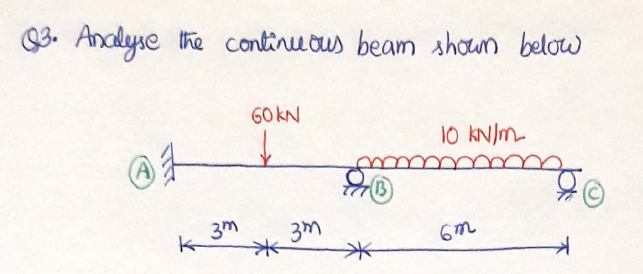
Let us start the example with a simple symmetrical parabolic three-hinged arch, as shown below

The first step in the solution is to find reactions using equilibrium equations. As discussed in previous blog post, we need to apply equilibrium equation 1) on the whole arch and 2) on the portion of arch separated at the internal hinge. The first part of this step is shown below

Horizontal force equilibrium is shown below


Moment equilibrium is applied as shown below

 NOTE that when the supports are at the same level, the horizontal reaction at B does not cause a moment at A.

Now, we need to apply equilibrium on the portion CB, separated at the location of internal hinge
NOTE: It is easy to always follow the strategy of taking moment about A for whole arch ACB and taking moment about the internal hinge C for the portion CB. By doing like this we get two equations in terms of VB and HB. Other options will make the analysis more lengthy and cumbersome.

Now we got all the reactions and we can solve for internal forces. We only need to draw BMD. So, we need to get expression for Mx only. since there is one concentrated load, we need to cut a section on the left of the load and one section on the right side of the load as shown below. By applying moment equilibrium for each of these sections, we get two expressions for M.


For the above section, it is easy to apply equilibrium for the portion on the left of the section, since this FBD has only two forces whose moments contribute to Mx . If we consider the equilibrium of portion XB on the right side of the section, we need to take moments of three forces to get Mx.
 Note that for the section on the right side of the load W, it is easy to consider the equilibrium of the portion on the right side of the section.

For both the sections, expression for Mhas two terms. We can draw the BMD by superimposing the plots of the two terms, as shown below

NOTE that in the above figure, the blue colour diagram (triangle) represents the first term (i.e 60x  and 20(20-x)  ) of the expressions for Mx.The red color parabola describes the second term of the expressions (i.e., 40y). We need to substract the two terms. So, the overlapping part is to be cancelled. The net BMD consists of the blue portion (positive) and the red portion (negative)

NOTE: THe maximum positive BM occurs under the concentrated load (in this case). Its value needs to be evaluated and shown on the net BMD diagram.

This section presents more examples of determinate arch analysis


EXAMPLE 1UNSYMMETRICAL SEGMENTAL ARCH

 This is a segmental arch (an arch which is a part of a circle). Since the supports are at different heights, it is referred to as unsymmetrical arch.

The first step is to find the reactions, using 1) FBD of whole arch ACB and 2) FBD of portion CB
 NOTE; Unlike in arches with supports at same level, the moment about support A involves the moment caused by horizontal reaction (thrust) HB . Especially for such problems as this, it will be easier if we  take moment equilibrium for whole arch ACB and portion CB, such that both equations are in terms of two reactions (Here VB and HB). Alternate ways will make the problem lengthy.


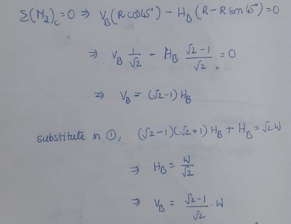
Now consider the moment equilibrium of portion CB of the arch
Note that the concentrated load at C will not make any difference in the equilibrium of portion CB

Note that the above solution became easier since both the equilibrium equations are in terms of VB and HB only, without involving VA

Now, we can determine the other reactions using the horizontal force equilibrium and vertical force equilibrium on the FBD of the whole arch shown previously


To determine the internal forces at a section, we need to cut a section at the required location and apply equilibrium equations on the FBD of the cut portion. Internal forces are first determined in terms of horizontal and vertical forces and then they are resolved in the tangential and normal directions to get normal thrust and radial shear respectively.
For transforming horizontal and vertical forces into tangential and radial directions, we need to know the angle made by the tangent with horizontal. If this angle is not given, we need to use the differentiation of the equation of the arch shape. In the present problem the angle made by the tangent is already given.
Note: The above transformation relationships between the internal forces is derived for the positive angle and so can be used for any part of the arch

EXAMPLE 2UNSYMMETRICAL PARABOLIC ARCH

The solution for this problem starts with sketching the figure showing all the details given in the question, as shown below

Now, consider the equilibrium of the whole arch, to evaluate the reactions


The above step is the only difficult part of the solution


For transforming horizontal and vertical forces into tangential and radial directions, we need to know the angle made by the tangent with horizontal. If this angle is not given, we need to use the differentiation of the equation of the arch shape. This is left for you as assignment. after determining the angle the calculations should continue as shown below

That's it. the solution is completed. For drawing BMD of the arch we can add the BMD caused by vertical forces and the BMD caused by horizontal forces.

Influence Line Diagram for moving load analysis


Influence line diagrams for static load analysis

  ILD are drawn for a single unit concentrated load travelling on the span/ structure. In the following video, I tried to explain the application of concept of ILD to the analysis of static/moving loads other than unit load, other than concentrated loads, and for multiple loads.


Influence line diagrams for trusses using the ILDs of beams

 The following video is for the students of II year B. Tech (civil Engineering) Programme. The video details the procedure for drawing ILDs of simply supported trusses


       In the following video, I tried to explain the procedure for drawing ILDs for member forces in trusses in which the top and bottom panel points are not vertically in line. In such trusses, a small correction needs to be done in the ILD. There should not be an abrupt change in the ILD at the point or section where the loading does not appear directly. So, that abrupt change at non-loading panel points needs to be smoothened.


Influence Line Diagrams using Muller-Breslau's principle

Influence line diagrams for beams from first principles

 Definition of Influence Line Diagram (ILD)

Deflections of beams and frames using Unit load method

 Unit load method is also based on energy principles, but slightly different in the approach. It is also known as principle of virtual work


Deflections of beams and frames using strain energy method

 Strain energy and castiglianos theorem

The following video is made for students of II year of Bachelor's programme in Civil Engineering